
ENGINEERING SIMULATION · CFD
Industrial Shed CFD Analysis: Solving Thermal Comfort in Data Centers
A practical, data-backed look at how Computational Fluid Dynamics predicts hot spots, airflow paths, and occupant comfort — before a single duct, louvre, or rack is installed.

Ask a facilities manager why a shed floor runs eight degrees hotter at the far end, or why a fully redundant CRAC system still can't stop one rack from throttling, and you'll usually get a shrug before you get an answer. Thermal comfort analysis using Computational Fluid Dynamics exists to replace that shrug with a number — and a fix. This article walks through how CFD is actually used to diagnose and design around heat, airflow, and comfort in two of the most demanding built environments there are: industrial sheds and data centers.
What Is Thermal Comfort Analysis?
Thermal comfort analysis is the engineering discipline of predicting whether people — or equipment — in a space will experience acceptable thermal conditions, and it goes well beyond checking a thermostat reading. A room can sit at a technically correct 24°C average and still be miserable, if half of it is a stagnant hot pocket and the other half sits in a cold draft near an intake louvre. That's the gap CFD is built to close: it doesn't just report an average temperature, it maps the entire three-dimensional field of temperature, air velocity, humidity, and radiant heat, cell by cell, across the whole volume.
The results are then converted into standardized comfort metrics rather than left as a color-coded picture:
- PMV (Predicted Mean Vote) — a scale from −3 (cold) to +3 (hot) predicting the average thermal sensation of a group of occupants, based on air temperature, radiant temperature, air speed, humidity, metabolic rate, and clothing insulation.
- PPD (Predicted Percentage of Dissatisfied) — derived directly from PMV, this estimates what percentage of occupants will find conditions uncomfortable even at an "ideal" PMV of zero, some dissatisfaction is unavoidable, and codes typically target PPD below 10–20%.
- Draft rate — the percentage of people predicted to be bothered by localized air movement, which matters most near louvres, fans, and diffusers.
- Vertical temperature gradient — the difference between ankle-height and head-height temperature, a common source of complaints even when the space-averaged temperature looks fine.
WHY THIS MATTERS COMMERCIALLY
A thermal comfort study isn't a compliance formality. In industrial facilities, poor thermal conditions measurably increase worker error rates and reduce concentration, while in data centers, localized hot spots are the single most common cause of unplanned equipment throttling and premature hardware failure. CFD turns both risks into a design decision made on paper, not a support ticket made in production.
Industrial Shed CFD Analysis: Where the Heat Actually Goes
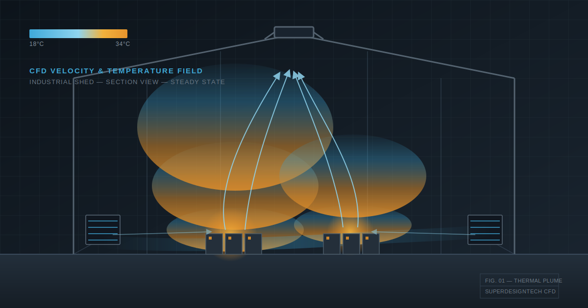
Industrial sheds present a distinctive thermal problem: large, often naturally ventilated volumes with concentrated heat sources — furnaces, compressors, ovens, motors, or simply a metal roof absorbing solar radiation all day — and a workforce that has to stand inside that volume for a full shift. Unlike a sealed office building, a shed's thermal behavior is dominated by buoyancy-driven airflow: hot air rising off machinery and off the underside of the roof, and cooler air being pulled in through low-level wall openings to replace it.
CFD modeling of an industrial shed typically resolves the following, all simultaneously:
-
Solar and process heat loads
Roof solar gain, radiant heat from machinery surfaces, and convective heat from process equipment are all applied as boundary conditions, since each drives a different plume shape and intensity.
-
Natural or mechanical ventilation paths
Wall louvres, roof monitors, ridge vents, and any exhaust fans are modeled as actual openings with real discharge coefficients, not simplified as a single "air change per hour" number.
-
Buoyancy-driven stratification
The simulation predicts how hot air layers form under the roof and whether that stratified layer is thick enough to reach the ridge vent, or whether it re-circulates back down into the occupied zone — the single most common design failure in shed ventilation.
-
Occupied-zone comfort mapping
Results are sampled specifically at 1.1–1.7 m height (seated to standing occupant zone), not at the roof apex, because that's where PMV/PPD actually matters for the people working the floor.
One structural detail that shows up again and again in shed CFD studies: exhaust alone is rarely sufficient. A field and simulation study on wind-driven roof exhaust in industrial warehouses found that roof exhaust fans removed thermal load efficiently but did not, by themselves, guarantee acceptable occupant-level thermal comfort — the geometry and placement of make-up air inlets mattered just as much as the exhaust capacity itself. That's a finding CFD catches at the design stage; a site survey after the building is finished mostly just confirms the complaint.
"The study in the design phase and the verification of details by means of CFD simulation are important to prevent future problems of unhealthiness and thermal discomfort in industrial buildings." — Findings consistent with published research on industrial shed roof ventilation and thermal comfort
Data Center CFD: Hunting Hot Spots Before They Exist
A data center is the inverse problem: instead of one large naturally ventilated volume, it's a tightly controlled, mechanically cooled space where the acceptable temperature band is narrow and the cost of getting it wrong is immediate hardware throttling or failure. Here, Data Center CFD models airflow between CRAC/CRAH (Computer Room Air Conditioning/Handling) units, raised-floor plenums, perforated tiles, rack rows, and containment barriers to answer one operational question: does every rack get the cold air it needs, and does no rack recirculate hot exhaust back into its own intake?
| Design Question | What CFD Predicts | Typical Risk If Skipped |
|---|---|---|
| Rack inlet temperature | Front-of-rack temperature at every U-position, aisle by aisle | Localized hot spots and ASHRAE envelope violations |
| Containment strategy | Cold-aisle vs. hot-aisle containment performance, bypass air % | Recirculation, wasted cooling capacity, higher PUE |
| Rack density increase | Whether existing CRAH capacity supports higher kW/rack | Retrofit failure, emergency shutdowns under load |
| Failure scenarios | Time-to-critical-temperature if a CRAH unit trips offline | Unknown thermal runway during outages |
The industry's own trajectory backs this up directly: full hot-aisle/cold-aisle containment — where cold supply air has only one possible path, from the cooling unit, through the rack, and back to the cooling unit — became standard specifically because uncontained layouts kept losing cooling capacity to recirculation and bypass air that CFD modeling exposed early. Reducing the total air volume needed, while eliminating the mixing that caused hot spots in the first place, is a direct, measurable outcome of running the simulation before construction rather than after.
Academic and applied case studies reflect the same pattern at a more granular level. One recent CFD study of a high-density data center, built and validated against a real reference facility in ANSYS Fluent, found that implementing cold-aisle containment reduced maximum rack temperatures by nearly 34% and eliminated hot-spot formation entirely — then went on to use the same model to test alternating high/low-density rack arrangements, identifying the configuration that cooled most uniformly before any physical retrofit was attempted.
A NOTE ON WHY THIS IS AN INDUSTRY STANDARD, NOT A LUXURY
As one industry research VP put it plainly regarding data center CFD: "It's well worth the cost to identify potential hot spots ahead of time. If your consultant doesn't think it's necessary, get another vendor who will assist you with this." CFD has moved from a specialist add-on to a baseline expectation in serious data center design and capacity planning work.
How a CFD Thermal Study Actually Runs, Step by Step
Whether the subject is a shed roof or a data hall, the underlying CFD workflow follows the same structure. Here's what SuperDesignTech's process looks like in practice:
-
Geometry & boundary condition setup
The building or room geometry is cleaned and simplified for simulation, and every heat source, opening, fan, rack, or diffuser is assigned a real boundary condition — heat load in watts, airflow rate, temperature setpoint — sourced from equipment datasheets or design specifications, not assumed defaults.
-
Mesh generation
The volume is divided into a computational mesh, refined most heavily near heat sources, inlets, and occupied or equipment zones where gradients are steepest and accuracy matters most.
-
Solving the governing equations
The solver iterates the Navier–Stokes equations for conservation of mass, momentum, and energy, along with a turbulence model and, for buoyancy-driven flows, a thermal buoyancy model, until the solution converges to a stable result.
-
Post-processing & comfort metrics
Raw temperature and velocity fields are converted into the metrics that actually answer the design question: PMV/PPD contours for occupied zones, rack inlet temperature tables for data halls, or hot-spot location maps for either.
-
Scenario comparison & recommendation
Because the model is virtual, alternative designs — a repositioned louvre, an added containment panel, a different rack layout — are tested against the same baseline, and the report recommends the option with the best comfort or thermal margin per unit of added cost.
Software Behind the Simulation
The right tool depends on the scale and specificity of the problem. General-purpose CFD solvers like ANSYS Fluent and ANSYS CFX handle both industrial shed airflow and custom data center geometries with full control over turbulence and buoyancy modeling. Autodesk CFD is commonly used for building-scale HVAC and thermal comfort studies, including ASHRAE 55 compliance checks. For data-center-specific work, purpose-built platforms such as Future Facilities 6SigmaDCX and Schneider Electric's EcoStruxure IT add rack-level libraries and capacity-planning features on top of the same underlying CFD math, which speeds up iteration when the question is specifically about rack layout and cooling capacity rather than building-wide airflow.
Frequently Asked Questions
What is thermal comfort analysis in a CFD study?
It's the process of modeling temperature, air velocity, humidity, and radiant heat throughout a space with CFD, then converting those results into standardized comfort indices like PMV and PPD so engineers can judge whether occupants will actually feel comfortable — not just whether the space-averaged temperature falls within a target range.
Why is CFD used for data center thermal design?
CFD models airflow between cooling units, raised floors, rack rows, and containment barriers to locate hot spots and wasted "bypass" air before construction, letting engineers test containment strategies and density changes virtually rather than discovering problems after the facility is live and under load.
How is CFD analysis different for an industrial shed compared to a data center?
A shed is typically naturally or mechanically ventilated at building scale, with heat from machinery, process equipment, or solar roof gain, and the goal is worker thermal comfort and code compliance. A data center is a tightly controlled, mechanically cooled space where the goal is protecting IT hardware from overheating. Both rely on the same CFD fundamentals, but the boundary conditions, target metrics, and acceptance criteria differ.
What software is used for industrial shed and data center CFD analysis?
Common choices include ANSYS Fluent and ANSYS CFX for general-purpose modeling, Autodesk CFD for building and HVAC airflow, and data-center-specific platforms like Future Facilities 6SigmaDCX and Schneider Electric's EcoStruxure IT for rack-level thermal work.
How long does a CFD thermal comfort study typically take?
A single-scenario steady-state study for a shed or data hall generally takes one to three weeks, covering geometry cleanup, meshing, solving, and reporting. Studies that compare several design scenarios, or that require transient (time-based) analysis, take longer.
Considering a CFD study for your facility?
SuperDesignTech's engineering team runs thermal comfort and airflow CFD studies for industrial sheds, warehouses, and data centers — from single-scenario hot-spot diagnostics to full containment and capacity-planning models.
Request a CFD Consultation →
0 Comments
Be the first to share your thoughts on this article.
Leave a Comment