
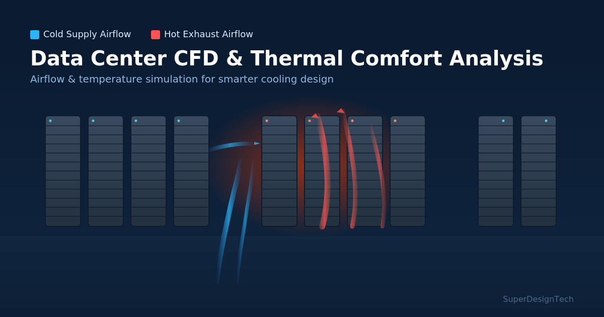

CFD-based temperature contour simulation illustrating hot aisle / cold aisle airflow inside a data center.
Thermal Comfort Analysis in Data Centers: How CFD Optimizes Cooling Design
Hotspots, uneven airflow, and rising energy bills are the silent risks inside every data center. Discover how Thermal Comfort Analysis powered by Computational Fluid Dynamics (CFD) helps engineers predict, prevent, and permanently fix these problems before they hit uptime.
Every data center operator faces the same underlying question: is the cooling system actually doing its job everywhere in the room, or just on paper? A single undetected hotspot near a high-density rack can trigger thermal throttling, hardware failure, or an unplanned outage. This is exactly the problem that Thermal Comfort Analysis, backed by Computational Fluid Dynamics (CFD), is designed to solve — and it has become one of the most valuable engineering services for modern data center design, retrofit, and capacity planning projects.
What Is Thermal Comfort Analysis in a Data Center?
Thermal comfort analysis is the engineering study of how air temperature, airflow velocity, humidity, and heat distribution interact within a defined space. In commercial and residential buildings, this typically means occupant comfort. In a data center, "comfort" refers to keeping IT equipment within its safe operating envelope — most commonly the ASHRAE TC9.9 recommended inlet temperature and humidity ranges — at every single rack, not just at the room average.
A room can show a perfectly acceptable average temperature on a building management system (BMS) dashboard while individual racks are quietly overheating. Thermal comfort analysis exposes these hidden variations by modeling the space in far greater detail than sensor readings alone ever can.
Why Computational Fluid Dynamics (CFD) Is the Right Tool for the Job
Computational Fluid Dynamics is a simulation method that solves the governing equations of fluid flow and heat transfer across a digital model of your facility. For data centers, CFD converts architectural drawings, rack layouts, CRAC/CRAH unit specifications, and IT load data into a 3D airflow and temperature model of the entire white space.
The output is not a guess — it is a visual, quantifiable map of:
- Airflow velocity and direction at every rack inlet and outlet
- Temperature contours across hot aisles, cold aisles, and containment zones
- Recirculation and bypass airflow that wastes cooling capacity
- Pressure differentials across raised floors, perforated tiles, and containment panels
- Predicted hotspots before a single server is powered on
Key Benefits of CFD-Based Thermal Comfort Analysis
1. Eliminate Hotspots Before They Cause Downtime
CFD identifies underperforming zones during the design stage, allowing engineers to correct rack placement, tile perforation ratios, or containment strategy long before installation — avoiding costly rework and unplanned service interruptions.
2. Reduce Cooling Energy Consumption and PUE
Over-provisioned cooling is one of the largest hidden costs in data center operations. Simulation reveals exactly where airflow is being wasted, enabling right-sized CRAC/CRAH deployment and measurable reductions in Power Usage Effectiveness (PUE).
3. Validate Hot Aisle / Cold Aisle and Containment Strategies
Whether you are evaluating hot aisle containment (HAC), cold aisle containment (CAC), or an in-row cooling approach, CFD lets you test and compare strategies virtually, quantifying the performance difference before committing capital.
4. Support High-Density and AI/GPU Rack Deployments
As rack densities climb with AI and GPU workloads, thermal margins shrink fast. CFD-based thermal comfort analysis is essential for validating whether existing infrastructure can safely absorb higher kW-per-rack loads, or whether liquid cooling integration is required.
5. Ensure Compliance and Uptime Institute / ASHRAE Alignment
Simulation results provide documented evidence that a facility design meets ASHRAE thermal guidelines and supports Uptime Institute Tier certification requirements — valuable for both compliance audits and stakeholder reporting.
The CFD Workflow: From Drawings to Actionable Results
| Step | What Happens |
|---|---|
| 1. Data Collection | Architectural drawings, rack elevation plans, IT load schedules, CRAC/CRAH specs, raised floor and containment details |
| 2. 3D Model Build | Digital replica of the white space, racks, cooling units, and airflow pathways |
| 3. Boundary Conditions | Heat load per rack, supply air temperature/flow rate, tile perforation %, containment geometry |
| 4. Simulation Run | CFD solver computes airflow, pressure, and temperature fields across the entire room |
| 5. Analysis & Reporting | Hotspot identification, recirculation mapping, PUE impact, and design recommendations |
| 6. Design Optimization | Iterative "what-if" scenario testing to finalize the most efficient, resilient layout |
Best Practices for Getting Accurate Thermal Comfort Results
- Use actual (not nameplate) IT heat loads wherever possible for realistic predictions.
- Model containment leakage and door/gap losses — they materially affect results.
- Validate the CFD model against live sensor data when retrofitting an existing facility.
- Re-run simulations whenever rack density, layout, or cooling infrastructure changes.
- Combine thermal comfort analysis with energy modeling for a complete efficiency picture.
Conclusion
Thermal Comfort Analysis powered by Computational Fluid Dynamics has moved from a "nice to have" to a core requirement for any data center that wants to guarantee uptime, control energy costs, and future-proof itself against rising rack densities. Instead of reacting to overheating issues after they occur, CFD lets engineering teams see the problem before it exists — and solve it on a screen instead of in a live facility.
Planning a new data center, expansion, or high-density retrofit?
SuperDesignTech's CFD engineering team delivers detailed Thermal Comfort Analysis and Data
Center CFD studies to help you eliminate hotspots, optimize cooling design, and reduce PUE
before construction begins.
0 Comments
Be the first to share your thoughts on this article.
Leave a Comment